Last Updated on March 16, 2024
Circuit diagram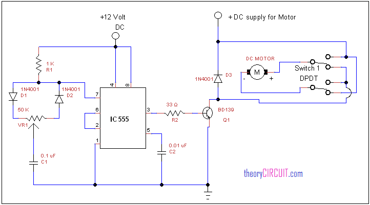
Construction and Working
In this website we already published about Speed control of DC motor with timer IC, here this circuit constructed for the basic motive to meet the forward / Reverse operation of DC motor with speed control.
The DC motor is connected to the supply through DPDT ( double pole double through ) switch, by changing the switch position we can get forward and reverse rotation from the DC motor because this switch interchanges power supply polarity applied to the DC motor.
The diode D1 protects the DC motor from the back emf effect hence there is no output load effect rise. The NPN transistor BD 139 drives the output from timer IC, this output pulse duration decides the speed of DC motor, by varying the VR1 resistor we can vary the pulse output of timer.
![]()
What is the function of D1 and D2 at pin7?
The HIGH Output will cause C1 capacitor to be charged through the R1 and D1 path. Upon C1 voltage reaching 2/3 of +V, the Threshold (pin 6) will be activated and drive the Output (pin 3) LOW. Discharge (pin 7) goes LOW. The time it takes for C1 to charge depends on the position of R1.
Since Output (pin 3) is now LOW, capacitor C1 will start to discharge through the D2 and R1 path. When the voltage of C1 drops below 1/3 of +V, Trigger (pin 2) will be LOW, driving Output (pin 3) to go HIGH, and Discharge (pin 7) to go HIGH and shorts to ground. The cycle repeats itself.
Hi there I am new to electronics but I think I could build this circuit, would this circuit carry enough current to power a 12v drill motor and rotate a small antenna mast with the right gearing, or would I need to change the circuit? thank you